
Analog & Digital Filters Design Project:
“Electric Guitar Pedal as a Rudimentary Introduction to Signal Processing, Linear Systems, Analog Filter Design, and Applications of These Concepts”
This was originally written December 13, 2005 as part of an undergraduate course project. It showcases the design of a custom guitar pedal while also serving as a tutorial in Fourier analysis and analog filter design.
Don’t feel like reading? Hear a clip! (Clean guitar at beginning; pedal starts at ~9 sec.)
Still don’t feel like reading? Look at some pictures!
Feel like reading now? Look at some words!
Overview
Guitar pedals manipulate the sound of the instrument in a variety of ways, covering a wide range of effects useful for any style of music. Aside from simple amplification and equalization, guitar pedals can also provide effects such as tremolo, overdrive, phaser sweeping, reverb, and vibrato. Especially with the advent of multi-effect digital guitar pedals, the potential effects, applications, and various chained combinations of guitar pedals allows for a vast amount of experimentation and creativity with music.
Of particular interest to the rock guitarist is the distortion pedal. While the music itself may be classified as unconventional or radical, the basic design of the pedal that drives modern rock also crosses boundaries—namely, certain preconceptions in the basics of electronic design. For instance, the electrical engineering student is told repeatedly that a transistor or amplifier is effectively useless under saturation—that saturation is merely a non-ideal characteristic of amplification circuits, since it causes clipping in the signal. However, the distortion guitar pedal uses this effect to its own advantage; the signal is purposefully clipped. This, in conjunction with certain other elements, produces a more squared-off signal at the output, effectively creating a crunched, rough, heavy tone.
I. Introduction
The project described by the following is effectively an exercise in both filter design and teaching. At the surface, it involves the design, simulation, construction, and demonstration of an electric guitar pedal, which utilizes the theory behind linear systems and filter design. Additionally, the device itself is used as a tool to introduce basic electronics, linear systems, and filter design to students—the approach used in teaching these subjects is intended for students in the first or second year of the electrical engineering curriculum. Ultimately, the guitar pedal is intended to showcase the utility of systems and filter theory, serving as an example of practical application of classroom knowledge.
The section labeled II. Fundamental Background provides a very basic explanation of frequency-domain analysis, basic electronics, linear systems, and filter design. The explanation is by no means thorough—it is not intended to provide deep insight into the underlying mathematical theory, the non-idealities of components used in analog filter design, or more advanced topics such as transfer function poles and zeros, feedback, or the quality factor of a circuit. Rather, the section is enough to introduce entry-level students to concepts seen in their junior- and senior-level classwork.
Section III. Application-Specific Theory and Implementation explains some concepts related to the design procedure, harmonic and intermodulation distortion, and audio-based applications. The section also includes schematics and simulation results.
The guitar pedal itself contains two stages: pre-distortion equalization and amplification/cutoff. The amplification/cutoff stage amplifies the input signal and cuts off its peaks—the result is a more squared-off wave, which produces a hard-edged, gritty sound by nature of the harmonic distortion produced by the act of clipping the waveform. The equalization stage comes before the amplification/ cutoff stage; it effectively controls the level of distortion and how the distortion effect varies by the pitches of the notes played. As explained in the section, the design decision to include filter-based equalization also provides for greater flexibility and more complicated chords while avoiding some of the non-ideal behavior inherent in synthetic distortion.
Sections V. The Pedal in Practice and VI. Optimization and Conclusion explain how the simulation compares to the actual pedal and how the design and implementation of the pedal can be improved or modified for other applications.
Since the pedal is intended to double as a teaching tool, the design is kept relatively simple; however, it is still highly functional and serves its purpose well as a pedal.
II. Fundamental Background
IIa. Introduction to Frequency Domain Analysis
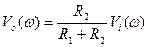
Any signal (e.g. voltage, current, or temperature) can be represented as a time-varying quantity—a function of time. Though Fourier analysis, signals can also be represented as the summation of an infinite number of sinusoids at different frequencies, then plotted as a function of frequency in the frequency domain. A plot of a signal in the frequency domain shows how much of the signal lies at specific frequencies. The most basic example is that of the simple sinusoid, ![]() , as shown in Figure IIa.1.
, as shown in Figure IIa.1.
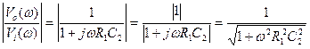
Note: ![]() is known as angular frequency, defined as 2
is known as angular frequency, defined as 2![]()
![]() times the frequency f of a sinusoid. The definition of angular frequency merely helps to condense certain definitions, terms, and functions. Whereas frequency f is usually expressed in Hertz (Hz), angular frequency is expressed in radians per second.
times the frequency f of a sinusoid. The definition of angular frequency merely helps to condense certain definitions, terms, and functions. Whereas frequency f is usually expressed in Hertz (Hz), angular frequency is expressed in radians per second.
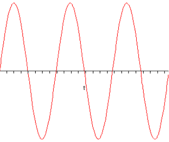
Figure IIa.1
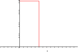
Of course, this signal is composed of a single frequency, ![]() . In the frequency domain, it is represented as a single strong line, infinite in height, at that frequency:
. In the frequency domain, it is represented as a single strong line, infinite in height, at that frequency:
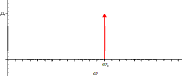
Figure IIa.2
Figure IIa.3 shows a plot of ![]() :
:

Figure IIa.3
Since x(t) is a summation of two sinusoids, it can be represented as two single lines in the frequency domain. Each line is still considered to be infinite in height, but each has a different strength depending upon the amplitude of the sinusoid at that frequency. Figure IIa.4 shows the plot of x(t) in the frequency domain:

Figure IIa.4
As stated, any signal can be decomposed into an infinite summation of sinusoids at various frequencies. The Fourier Series of a periodic signal provides exactly that—it allows a signal to be represented in the following form:

This can also be expressed in summation form as follows:

In the expressions above, c0, c1, c2, … and ![]() 0,
0, ![]() 1,
1, ![]() 2, … are constants, and
2, … are constants, and ![]() 0 is known as the signal’s fundamental frequency. Generally, a plot of a signal in the frequency domain will consist of an infinite number of vertical lines at integer multiples of the fundamental frequency.
0 is known as the signal’s fundamental frequency. Generally, a plot of a signal in the frequency domain will consist of an infinite number of vertical lines at integer multiples of the fundamental frequency.
Take the periodic sawtooth waveform shown in the figure below:
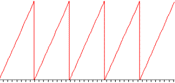
Figure IIa.5
Its Fourier Series representation is given by the following:

From this, a plot of the signal in the frequency domain yields the plot shown in Figure IIa.6. Notice how the plot decays—this is due to the fact that each succeeding harmonic is increasingly dampened (the coefficients decrease in magnitude as the harmonic number increases).

Figure IIa.6
Figure IIa.7 shows another periodic signal, a square wave, represented both in the time domain and frequency domain:
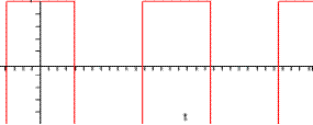
![]()

Figure IIa.7
Fourier analysis is widely used by engineers as a tool to accomplish some certain end goal. Since any signal can be represented as a function of frequency rather than time, it becomes much easier to design a circuit or system to manipulate the frequency content of the signal—for example, if a human voice cannot be understood due to high-frequency noise, one can design a low-pass filter to extract lower frequencies containing the voice while blocking the high-frequency noise.
From an engineering standpoint, however, most signals that need to be processed, such as the human voice, are in fact not periodic. Fortunately, Fourier analysis can easily be extended to cover these nonperiodic signals—this is accomplished by assuming that the signal has an infinite period. Theoretically, the fundamental frequency of a nonperiodic signal, then, approaches zero. This yields a summation of sinusoids with frequencies spaced infinitely close together, which can be shown to condense to an integral:

X(![]() ) is known as the Fourier Transform of x(t), and it is given by the following:
) is known as the Fourier Transform of x(t), and it is given by the following:

The Fourier Transform provides a way to express any signal—whether it is periodic or not—in the frequency domain. While the frequency content of periodic signals will contain discrete lines at various frequencies, nonperiodic signals will instead be represented on a continuous spectrum in the frequency domain. Figure IIa.8 shows a simple single pulse and its frequency content:
![]()
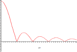
Figure IIa.8
The implication that any signal can be represented as a function of frequency makes filtering much easier to understand and to conceptually visualize. Since signals can be decomposed into combinations of sinusoids, we can also utilize the linearity of a system or filter, essentially passing each individual sinusoid of an input signal (with its corresponding amplitude and phase shift) through the filter and recombining them at the output, forming a transformed version of the input signal.
IIb. Electric Circuit Analysis and Passive Filters
To move from concept to implementation, it is helpful to look to AC (sinusoidal/time-varying) circuit analysis and the tools that help to simplify it. Engineers can design basic filters (like the example low-pass filter described in section IIa) by a proper combination of simple circuit elements, such as resistors and capacitors. The voltage-current relationships of a resistor and capacitor are given by the following, respectively:

These voltages and currents are time-based signals, and, just like any other signal, they can be represented as a function of frequency:
The impedance of circuit elements is the ratio of voltage to current—it can be thought of as a generalized resistance. Impedance is denoted as Z; for a resistor and capacitor, it is given by the following:
A resistor’s impedance is equivalent to its resistance. The impedance of the capacitor, on the other hand, is inversely proportional to frequency—that is, at low frequencies, its impedance is high, while it drops at high frequencies. By this concept, resistors and capacitors can be combined to pass and block frequencies as desired. The notion of impedance is also used to simplify analysis of circuits that take AC input.
To combine basic circuit elements and create a system or filter, it is helpful to start from the basics; the voltage divider comes from basic DC circuit analysis, and it serves as a good starting point for basic filter design. Figure IIb.1 shows the circuit diagram for a simple voltage divider:

Figure IIb.1
The current i through the closed loop can be found through Ohm’s Law. Since vo is merely taken as the voltage across R2, it can be found by:


In analyzing a system or filter, engineers often look at its transfer function, which is the ratio of the output of a system to its input in the frequency domain. Finding the transfer function of Figure IIb.1 is a simple matter of transforming all time-varying quantities from the time domain to the frequency domain.
The transfer function itself is found by dividing both sides of the expression by ![]() , yielding the following:
, yielding the following:
From the circuit’s “transfer function,” it is apparent that the ratio of the circuit’s output to its input is constant over frequency—this is due to the fact that the impedance of a resistor does not depend upon frequency. From a system-oriented perspective, the simple voltage divider always provides this output-input ratio, independent of the frequencies contained in the input signal.
Of course, the simple voltage divider does not modify the frequency content of a signal (and, as such, the term “transfer function” may be inappropriate for the case of the voltage divider). However, the circuit serves as a starting point for certain modifications that do perform frequency filtering. In Figure IIb.2, R2 is replaced by a capacitor of value C2:
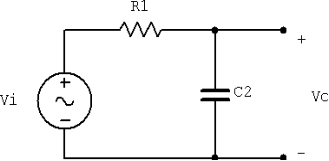
Figure IIb.2
In the circuit above, one can find the value of vo by the impedances of the resistor and capacitor. In the frequency domain (and in AC analysis), the input voltage is split between the elements, just as it is in the resistor-only voltage divider.
The transfer function is also found similarly, then simplified:

Since the impedance of a capacitor is an imaginary value, the transfer function is complex—it contains both magnitude and phase shift components. This discussion is concerned primarily with the magnitude of the transfer function, since the magnitude dictates how much of a given signal will pass through the filter. The magnitude of this circuit’s transfer function is given as follows:
In this case, the ratio between the output and input voltage depends on the frequency of the input signal. Figure IIb.3 shows a plot of the transfer function’s magnitude as it varies by frequency:
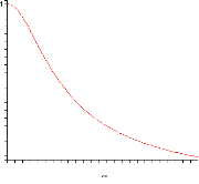
Figure IIb.3
The high-frequency components of the input signal are blocked by the filter, and its low-frequency components are passed through to the output. The circuit in Figure IIb.2 is a simple low-pass filter; at DC (where the frequency is zero), the magnitude of the output is equal to the magnitude of the input. The values of the resistor and capacitor determine the “width” of the filter.
This basic voltage division circuit can be transformed into a high-pass filter as well by swapping the resistor and capacitor:
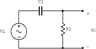
Figure IIb.4
This new circuit’s transfer function is given by the following:
Its magnitude can similarly be found and plotted (Figure IIb.5):
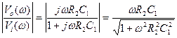
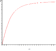
Figure IIb.5
At DC, the magnitude of the transfer function is zero; as the frequency increases, the magnitude increases (and asymptotically approaches unity). This filter passes high frequencies on to the output terminals and blocks low frequencies.
Resistors and capacitors are two of the major building blocks of filtering circuits. They can also be used in conjunction with other components to produce more sophisticated, versatile, and useful filters by allowing for a wider variety of transfer functions.
IIc. Operational Amplifiers in Filter Design
Another device that is often used in filter design is the operational amplifier or op-amp, which is a device that allows for a very high amplification. Depending on its connections to other components, its amplification can be adjusted for filtering purposes. Figure IIc.1 shows the circuit symbol for an op-amp:

Figure IIc.1
Ideally, Rin, the resistance between v– and v+, is infinite, and v– is equal to v+. Figure IIc.2 shows an op-amp in the inverting configuration, where the input signal is connected to v–:

Figure IIc.2
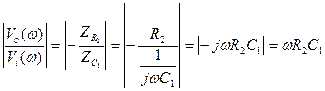
To determine the output-input ratio for the inverting configuration, it is helpful to take note of the ideal characteristics of an op-amp. Since v– and v+ are equivalent (and v+ is zero), the currents flowing through R1 and R2 are given by the following:

Moreover, since Rin is infinite, it acts as an open circuit; therefore, the current flowing through R1 is equal to the current flowing through R2. This yields the closed-loop gain of the inverting configuration:

For any input into the inverting configuration, the output will be multiplied by the ratio of the two resistors—and if R2 is greater than R1, the input will be amplified. As with the resistor-based voltage divider, this quantity does not depend upon frequency; however, it can also be used with capacitors to form a filter. Figure IIc.3 replaces R2 with a capacitor:
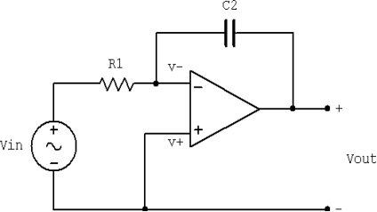
Figure IIc.3
The magnitude of the transfer function of this new configuration is as follows:

The transfer function decreases as the frequency of the input increases; it is another low-pass filter. Replacing R1 with a capacitor instead yields a high-pass filter:
The op-amp is an essential tool in filter design. With the op-amp and various choices of components and connections, a system can provide, for example, amplification at low frequencies while simultaneously removing high frequencies. Depending upon the configurations used, filters using op-amps can also be chained together to form more squared-defined cutoffs that, for example, can practically completely remove all frequencies above a certain cutoff while completely preserving frequencies below the cutoff.
III. Application-Specific Theory and Implementation
IIIa. Desired Behavior of the Pedal
The electric guitar pedal is intended to provide a very hard clipping of the input signal, producing a distorted signal with an electronic, synthetic bass appeal. This is accomplished by greatly amplifying the signal and limiting it to square off the wave, producing high-order harmonic distortion (discussed in section IIId). This distortion effect, however, is desired more at lower frequencies than higher frequencies; therefore, a low-pass filter is placed before this amplification. The filter serves to boost lower frequencies more than higher frequencies. At low frequencies, then, the filter further increases the distortion effect.

Figure IIIa.1
IIIb. Pre-Distortion Equalization Stage
The design of the pedal utilizes the inverting op-amp configuration with generalized, variable impedances, allowing the curve shape of the pre-distortion equalization’s transfer function to be adjusted. The configuration used by the pedal is as follows:
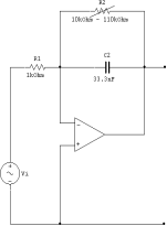
Figure IIIb.1
The magnitude of the transfer function for this subcircuit is given by the following:
The DC gain of this function is R2/R1, and the function approaches zero as the frequency increases.
The operating range of the pedal shall be limited between around 49.0 Hz (G1) and 1174.6 Hz (D6), rounded to a range of 0 Hz to 2 kHz to provide a well-defined margin in which to work. The components are chosen appropriately for the desired operating range: R1 is fixed at 1k, R2ranges from 10k![]() to 110k
to 110k![]() , and C2 is chosen to be 33.3nF. These values ensure that there exists a noticeable difference in the transfer function’s magnitude within this range.
, and C2 is chosen to be 33.3nF. These values ensure that there exists a noticeable difference in the transfer function’s magnitude within this range.
One concern in choosing an appropriate op-amp is the fact that, at very high frequencies, the amplification provided by an op-amp tends to decrease. However, since the largest operating frequency of the pedal is relatively low, the relatively inexpensive LM741 model op-amp can be used in the design.
With this choice of components, the DC gain of pre-distortion equalization stage ranges from 10 to 110, or 20 dB to 40.8 dB. The corner frequency, where the amplification decreases to 3 dB below the DC gain value, ranges from around 43.146 Hz to around 460 Hz. Figure IIIb.2 shows the Bode plot of this stage for the minimum and maximum values of R2, showing how the transfer function varies by frequency:

(left: minimum R2, right: maximum R2)
Figure IIIb.2
The general shape of the Bode plot over the desired range of operation is of great interest. Adjusting R2 “lifts” the curve at low frequencies while leaving high frequencies relatively unchanged—at 2 kHz, the gain remains almost constant, ranging from 7.3 dB to 7.537 dB in simulation. Thus, this pre-distortion equalization circuit yields the desired low-pass filtering, also providing the capacity to further boost low frequencies.
IIIc. Amplification/Cutoff Stage
The circuit in Figure IIIc.1 is the amplification/cutoff stage of the pedal. Included in this stage is a variable resistor Rv, which controls the volume of the pedal’s output.
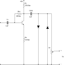
Figure IIIc.1
The input signal from the low-pass filter/low-frequency boost circuit is further amplified by the transistor. The two diodes then limit the amplitude of the signal to the forward voltage drop of the diode, effectively cutting it off at its peaks.
This process is shown in the figure below. The first block shows the input signal, the second shows the amplified signal (through both the low-pass filter and the transistor amplifier), and the third shows the resulting waveform:

Figure IIIc.2
Additionally, the more the input signal is amplified, the more “squared-off” it becomes:

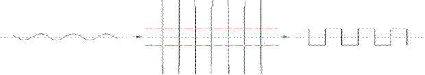
Figure IIIc.3
Therefore, since the low-pass filter amplifies lower frequencies much more than higher frequencies, the distortion effect will occur much more prominently at low frequencies. Note, too, that if the amplification does not push the waveform peaks higher than the diodes’ forward voltage value, the effect will essentially not take place at all. In the operation of the pedal, this occurs at higher frequencies or with small values of R2 at low frequencies.
IIId. The Principle of Harmonic Distortion
The square wave in Figure IIIc.3 is very similar to the square wave in Figure IIa.7. The former is produced by clipping a sinusoidal waveform, the latter by mathematics; namely, summing an infinite series of sinusoidal waveforms at ever-increasing frequencies.
Regardless of how a square wave is created, its frequency content remains the same. The amplification/cutoff stage of the pedal, then, also changes the frequency content of the input signal, introducing the higher-order harmonics seen on the frequency-domain plot in Figure IIa.7. These higher-order harmonics are known as the harmonic distortion of the underlying fundamental sine wave.
Observe as the Fourier series of the square wave more closely approximates the square wave as the number of harmonics (N) is increased:
In order: N=1, N=5, N=10, N=20, N=50

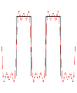


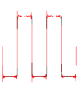
Figure IIId.1
Absolutely limiting a waveform to values within the clipping range produces a wave with a very flat top, and high amplification induces sharp corners in the waveform. As evidenced by the progression shown in Figure IIId.1, these corners are produced by the higher harmonics of the sinusoid.
IIIe. Intermodulation Distortion
Intermodulation distortion is an effect produced by playing two or more notes at once—clipping the waveform actually generates additional tones at the sum and difference of the notes’ frequencies. Depending upon the notes played, this effect can be desirable; with some simple chords (such as the “power chord,” a stylistic staple of the rock music genre), intermodulation distortion can generate tones that are in tune with the chord, helping to “flesh out” the resulting sound. However, in the case of more complicated chords, many additional tones are added to the mixture, some of which produce out-of-tune notes.
The effect of intermodulation distortion occurs to a greater degree with harder clipping (where the output waveform more greatly approximates a square wave). Therefore, to allow for more complicated chords, one can tone down the amount of clipping at the output. This, however, would reduce the pedal’s synthetic distortion effect that works well with single notes and simple chords.
The design of the pedal includes a low-pass filter at the input, which provides as a compromise between the overall harmonic distortion effect and the intermodulation distortion produced with such hard clipping. At low frequencies, the hard clipping, synthetic distortion effect is still present; however, as the frequency increases, the distortion effect begins to decrease. This allows for more complicated chords that utilize higher-frequency notes—these higher frequencies will contribute less undesirability to the resulting intermodulation distortion; however, the high frequencies will still be passed through to the output and recombined into a chord on the other end. While the undesirable aspects of intermodulation distortion are by no means completely avoided, they are toned down to a great degree due to this design decision.
IV. Simulation Results
The circuit simulation program Multisim 7 is used to simulate the circuit behind the pedal. Figure IV.1 shows the circuit as implemented in simulation:
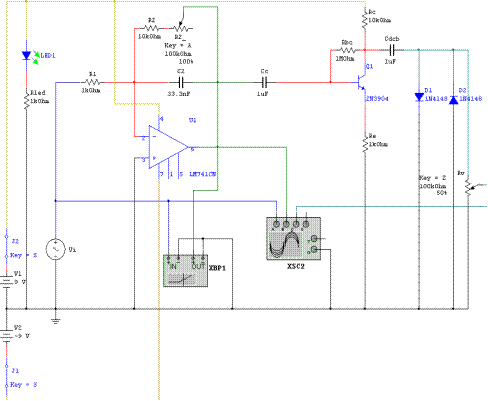
Figure IV.1
The simulation uses component models that match or are very close to the components used in the pedal itself, including the LM741 op-amp and the transistor and diode models shown in the figure above. Two back-to-back 9V batteries supply the needed +9V and -9V to the circuit.
The four-channel oscilloscope is tied to the input signal, the output of the pre-distortion equalization stage, and the output of the amplification/cutoff stage. In the figures below, the blue line, green line, and cyan line represent these waveforms, respectively.
At 20 Hz and a maximum value for R2, the oscilloscope plot appears as follows:
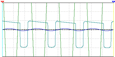
Figure IV.2
At this low frequency, the op-amp greatly amplifies the signal. At certain points, the transistor is pushed into saturation, which results in a waveform that does not quite conform to the “perfect square” shown in Figure IIIc.3. However, this is not detrimental to the sound of the output—it merely produces a bit of a different effect.
Figure IV.3 shows the same plot, this time with an input frequency of 200 Hz:

Figure IV.3
It is apparent that the op-amp provides less amplification at this frequency. The result of the amplification/cutoff stage, then, yields a more uniform square waveform with some rounding near the edges due to the small leakage and non-ideal turn-on transient of the diodes. This rounding effect is actually beneficial to a certain extent—it somewhat dampens the effect of intermodulation distortion, which, as explained in the previous section, is undesirable with complicated chords.
A 2 kHz input produces the following:

Figure IV.4
As to be expected, the op-amp provides very little amplification at such high frequencies. Therefore, the amplification/clipping stage has little to no effect upon the input; it passes a relatively clean sinusoidal signal.
Additionally, the respective position of each of the waveforms in the figures above indicates that there is a phase shift induced between the input and the output. This phase shift is due to the complex-valued impedance of the capacitors used in the circuit (including the coupling capacitors Cc and Cdcb). In this specific application, however, the resulting phase shift is not a concern.
The value of R2 also has an effect upon the resulting waveform. With R2 at a minimum, a 20 Hz signal produces the following output:
 Figure IV.5
When compared to Figure IV.2, this more closely approximates a square wave due to the decreased amplification provided by the low-pass filter.
V. The Pedal in Practice
The simulation matches up very well with the actual behavior of the pedal. Figure V.1 shows the output of the pedal as plotted on a real oscilloscope, given 20 Hz, 200 Hz and 2 kHz sinusoidal input signals. These are analogous to Figures IV.2-IV.4 in the simulation.
In order: f = 20 Hz, f = 200 Hz, f = 2 kHz
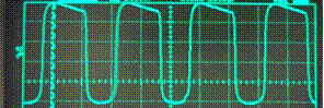
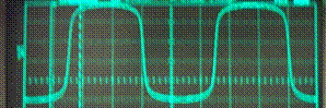
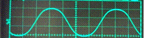
Figure V.1
While the simulation figures in section IV and the figure above both assume a simple sinusoidal waveform input, the input waveform of a guitar is in fact not a sine wave—it is actually closer to a sawtooth, which contains all harmonics at increasingly attenuated amplitudes. As provided by the audio recording and manipulation program Audacity v1.2.2, Figure V.2 shows a plot of an electric guitar waveform and its frequency spectrum.


Figure V.2
The nature of the frequency spectrum is quite close to that of Figure IIa.6 (the frequency spectrum for the ideal sawtooth wave in Figure IIa.5)—decaying as a function of frequency.
As previously discussed, due to the properties of linear systems, each harmonic can be treated as a separate sinusoidal waveform. Theoretically, then, each of the frequencies present in the input waveform is separately manipulated by the pedal and recombined at the output.
Figure V.3 shows the shape and spectrum of a single note from an electric guitar when passed through the pedal:


Figure V.3
Like the fundamental sinusoid of the input, harmonics present in the input are also amplified to some degree. Ultimately, this behavior lends a very different character to the sound at the output when compared to the sound of a simple, clean electric guitar.
VI. Further optimizations and conclusions
While the pedal described by the preceding sections functions as intended, its simple design does leave room for general improvement and modification. Such modifications could make the pedal more suitable and practical for normal use or allow for a different sound.
First and foremost, the pedal’s circuit is implemented on a small breadboard and utilizes a simple two-position switch to turn the device on and off:
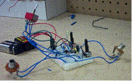
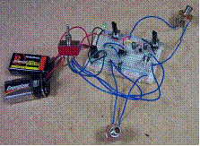
Figure VI.1
Obviously, this does not make for a rugged pedal, nor does it allow one to toggle the distortion effect very easily. The device could easily fit into a metal or plastic enclosure, and the switch, potentiometers, and quarter-inch cable interfaces can be mounted to the outside to provide a much sturdier pedal. Moreover, replacing the on/off switch with a toggle switch would provide the capability to switch the distortion effect as desired while playing.
Another design improvement involves the potentiometer that controls the output volume. The volume potentiometer chosen for the pedal (purely for its availability) is linear—its resistance increases or decreases linearly as a function of its dial position. However, since the human auditory system naturally uses a logarithmic scale, a linear potentiometer increases or decreases audio volume more rapidly near one extreme dial position than the other. Therefore, a logarithmic potentiometer would be a more suitable choice for the volume control.
The amplification/cutoff stage can also be tweaked to form a strikingly different sound at the output. Germanium diodes provide a softer clipping than those made of silicon—their forward voltage drop is less than that of silicon diodes, but they tend to be less restrictive in their clipping characteristics. This results in an output waveform that lies somewhere between a square wave and a sinusoidal wave. Silicon and germanium diodes can be combined in series or parallel to produce a multitude of possibilities for the output signal. Among other possibilities, this allows for asymmetrical clipping—where the top and bottom of a waveform are clipped differently—which is highly noticeable by the human ear.
Many pedals designed for rock distortion tends to use soft clipping to reduce the effect of intermodulation distortion described previously, generally providing more uniform distortion across the frequency band while still allowing for more complicated chords to be used with the pedal. This type of rock distortion, however, also has a markedly different sound than the synthetic distortion used in this synthetic distortion pedal.
While the simplistic pedal definitely has room for improvement, it does have its advantages as well. For one, parts for the entire pedal totaled just slightly over $10, very inexpensive when compared with pedals of similar functionality whose costs are tenfold or more. Additionally, with some slight tweaking at the output stage, the pedal can be chained to others to combine effects. Analog or digital filters inside more complicated pedals can provide a variety of such effects, which range from plain equalization to tremolo and phase-shifting.
The synthetic distortion pedal described herein provides a great amount of versatility and functionality in a very small, inexpensive package. Most importantly, it has proven that a design does not necessarily need to be overly complicated in order to function as desired. In fact, some such designs are simple enough to serve as teaching tools for future engineers.
